

RoboShark
This is a maker guide for creating a robotic shark that you can drive with an android mobile device. The body is comprised of three separate pieces of acrylic, that are surrounded with oscillating el-wire to give the appearance of motion/chomping as they flash. The base is built on top of the Cherokey 4WD robot chassis. This chassis will work with a variety of microcontrollers, of which I chose to use an Arduino Uno. Complete bill of materials and build instructions are included below. If you are going to fire in an recreate, please pre-read the lessons learned in the appendix so you can avoid some of my mistakes!
1) Parts and Equipment
| Part | Number | Total Cost ($) |
|---|---|---|
| Cherokey 4WD Robot Chassis | 1 | 50 |
| 7.4V Lipo battery | 1 | 20 |
| 12V Battery pack | 1 | 5 |
| Arduino Uno | 1 | 25 |
| Arduino Proto Shield | 1 | 10 |
| DF-Bluetooth Module v3 | 1 | 22 |
| el-wire: blue 2.5m | 3 | 60 |
| 12V el-wire inverter | 1 | 5 |
| Tinkerkit T010010 relay modules | 3 | 30 |
| Acrylic 1/8" blue | 4 | 100 |
| Acrylic cement + applicator | 1 | 10 |
| 28 gauge black steel wire | 1 | 5 |
| M2.5 screws and nuts | 50 | 10 |
| Other minor electronic odds & ends | ||
| Total: | 352 |
| Equipment list |
|---|
| Laser cutter (Trotech Speedy 300) |
| Soldering iron and basic competency |
| Digital multimeter |
| Cell phone (or other bluetooth device to use as controller) |
| PC to program arduino |
| Quickgrip clamps |
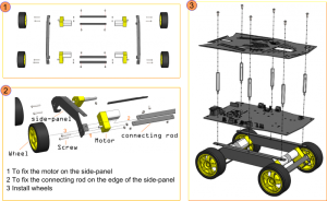
2) Assemble the chassis
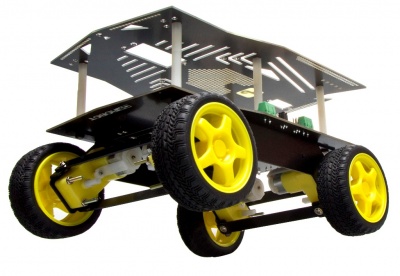
Assemble the chassis for the Cherokey 4WD robot according to the following document:
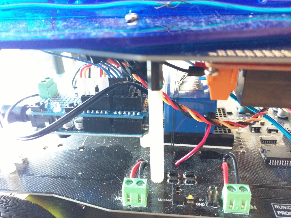
I made a few small modifications to the default build. First, I added an additional standoff to make the interior section slightly taller, to allow for a little more space for the relays, inverter, and Arduino shield.
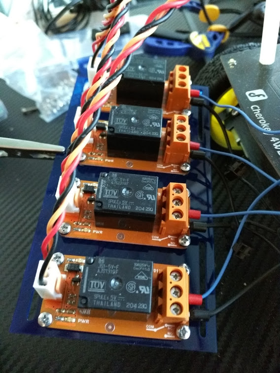
I made a small plastic piece to hold the relays in place. Originally I had 4 here, however 3 ended up being sufficient for the final project. These screw into the acrylic holes using M2.5 screws, then the whole assembly is screwed to the underside of the top plate of the Cherokey:
The inverter fits directly behind the Arduino in the center of the chassis, and can be affixed using small zip ties to hold it in place:
Circuit diagram
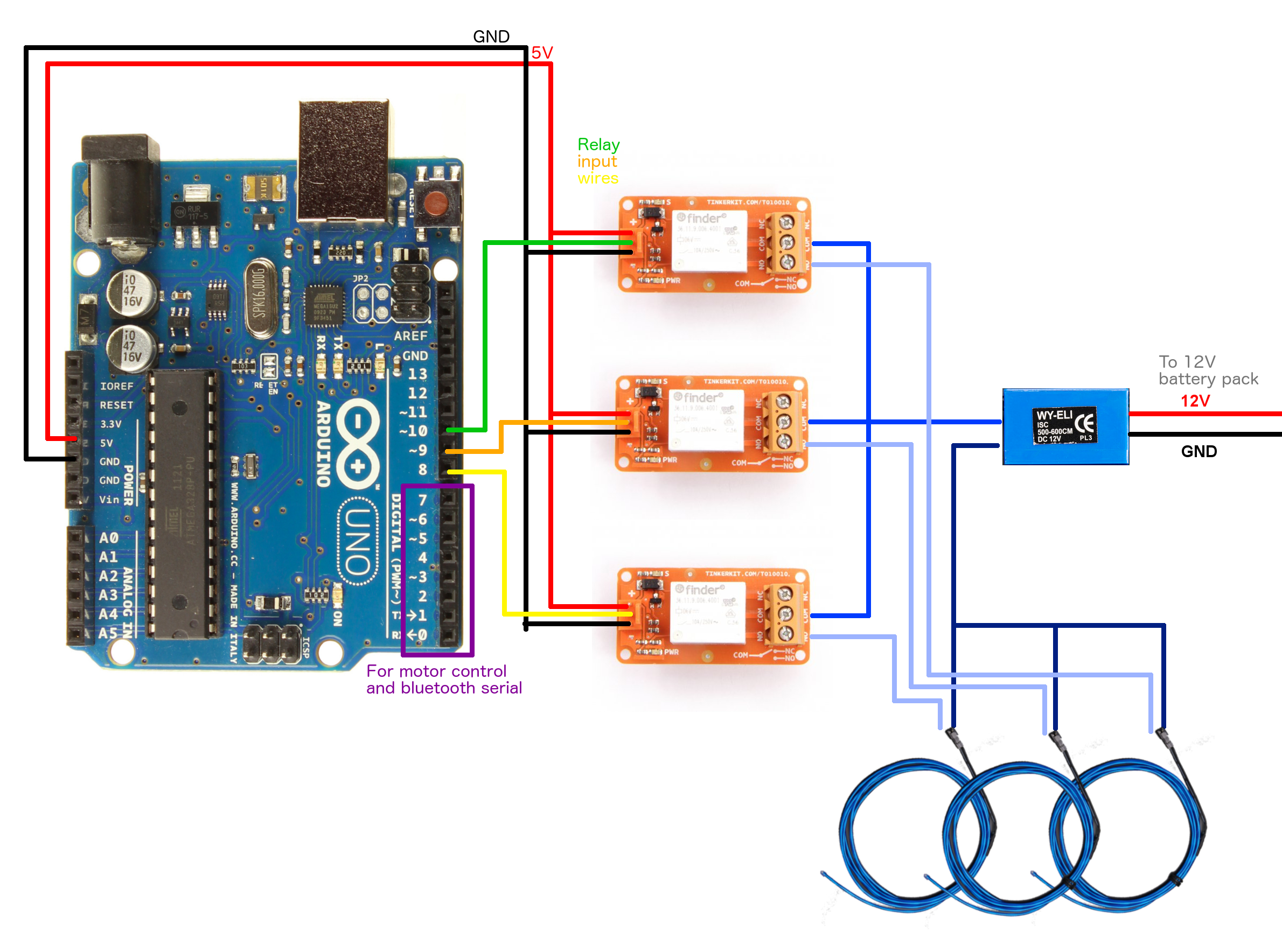
Relay wiring
Relays are essentially electrically operated switches. In normally open (NO) configuration, if the input signal goes high, it closes the switch, and vice versa when the input signal is low. Relays isolate the input trigger signal, from the switch on the right hand side. Here I chose a mechnical relay, which physically moves an internal component to connect the circuit. Other options include MOSFET relays, which are better for high speed switching (e.g. PWM) applications. The Tinkerkit relay shown here is discontinued I believe, but at the time of writing this article, there are still some in stock at Mouser. Any other mechanical relay should do just as well.
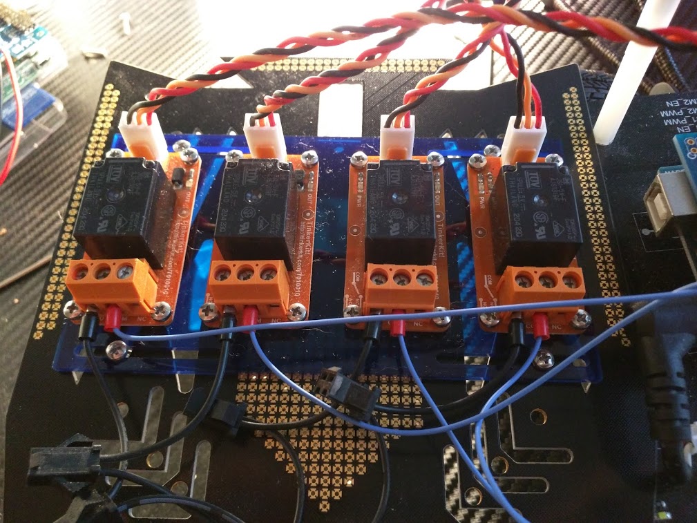
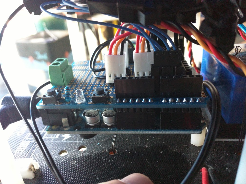
According to the diagram above, we need to provide +5V, Ground, and the input signal. For each relay, we also need to have the middle input pin connected to a digital output pin on the Arduino, such that we can control the state of the switch through software. These are shown as green, orange, and yellow wires in the diagram, and are connected t0 pins 8-10, as pins 0-7 were used for controlling motors and talking with the bluetooth adapter. In order to make the relay connections, I used the standard Tinkerkit wire, and soldered headers onto the Arduino shield for quick disconnect.
Additionally, we need to wire up the opposite end of the relay to turn on the el wire when the input wire is active. In order for the lights to be active, we need to complete the circuit with the inverter. The lights will turn off, if even one portion of that loop is broken. We will be using the relays in normally open position. This means that if there is no signal on the input, the switch is open, and the el wire is off. If the input wire on the left is active, the switch will be closed, and the el wire will light up. At the completion of this stage, we have three independent software addressable el wire pieces that we will later use to flash different shark outlines in sequence.
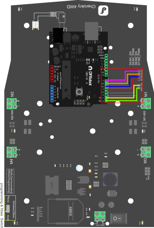
Motor / Bluetooth wiring
The Cherokey chassis has a nice PCB design for connecting your Arduino to the servos and bluetooth module. From their website, you can connect pins 0-7 as follows:
Software
The Shark Car relies on bluetooth communication to drive. Any bluetooth compliant device will work to send the appropriate signals. I used the open source offering from Silver Coder, who has kindly provided a free Android bluetooth application for driving robotic vehicles (Thanks!). You can find the code for it here:
https://play.google.com/store/apps/details?id=pl.mobilerobots.vacuumcleanerrobot&hl=en
Now, we need to implement the code to receive signals from this software. The DF Robot bluetooth module receives a single character for each of the directions, and we need to implement listening code to control the motors in a reproducible fashion based on each signal. Additionally, we need to develop a solution to simultaneously oscillate the relays to control the lights. The arduino does not do multithreaded software, so this is a bit of a hack, but it proved functional. Source code was modified from github user srebroa and found here:
Shark Body
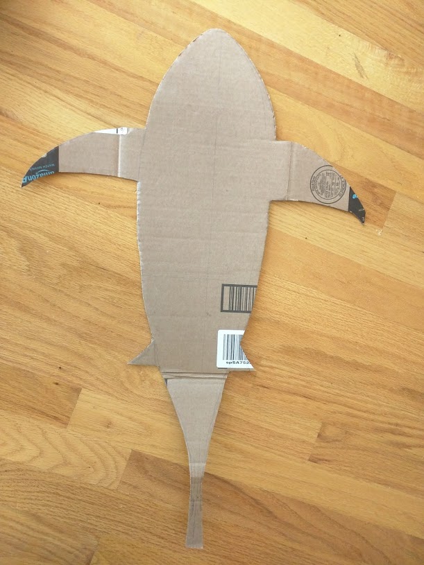
My wife designed the shark body. She first prototyped it using cardboard, to get the dimensions and center of gravity right.
Once she was happy with the design, she sketched up plans for the laser cutter in Illustrator. They are available on ThingVerse here:
http://www.thingiverse.com/thing:942809
For the body, we chose 1/8″ Acrylic sheet from Tap Plastics in SF. Their staff was really helpful and knowledgeable. If cost is a consideration, you could use alternative materials for this part.
To cut the design, we used a Trotec Speedy 400 at Techshop. For acrylic, you want to start at lower power/speed and figure out what settings provide a nice clean cut without melting or burning. For this we used the ‘holestest’ file included with the thingverse package. This also let us test the diameter of the holes which needed screws, to ensure a snug fit.
Once your settings are correct, you should keep the protective paper on the acrylic while you cut to prevent any smoke/burn marks. Always cut interior holes/features before the main body, as parts can shift once they are freed from the bulk piece of material. A video of the cutting process can be found below:
After you cut the raw pieces, it is time to assembly the shark body. For this task, we used acrylic cement and a needle applicator. If you put the acrylic pieces orthogonal to each other, then apply a small amount of the cement, the surface tension will pull it into the joint to form a tight bond. Note that this is a solvent, so it is essentially taking two pieces of material, and fusing them into one, as opposed to putting a third party substance between them to join them (like glue). After you have applied the cement to each piece, it will fuse with a weak bond within ~30 seconds. Let it sit overnight, preferably clamped down if possible, for it to fully cure and form a solid bond.
Once the acrylic body is properly fused, you can attach it to the chassis using m2.5 screws. Note that there are room for improvements with the design (described below). Note that you should plug in the three el-wire leads and thread them through the port on the chassis and body prior to screwing it down.
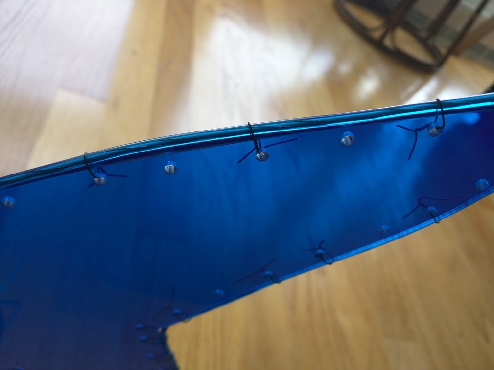
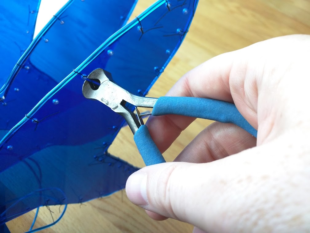
Once the body is attached to the chassis, you can start to affix the el wire to the holes using the steel wire. For each hole (or every other), set the el-wire on the surface of the acrylic, loop the steel wire around and through the hole, then twist it off to tighten it. After you have affixed all the el-wire, you can use pliers to cut off the excess steel wire to make things look neat.
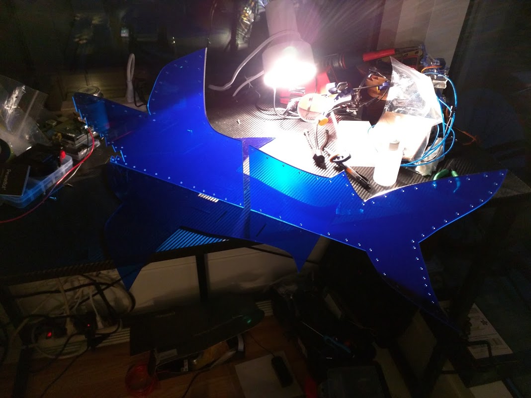
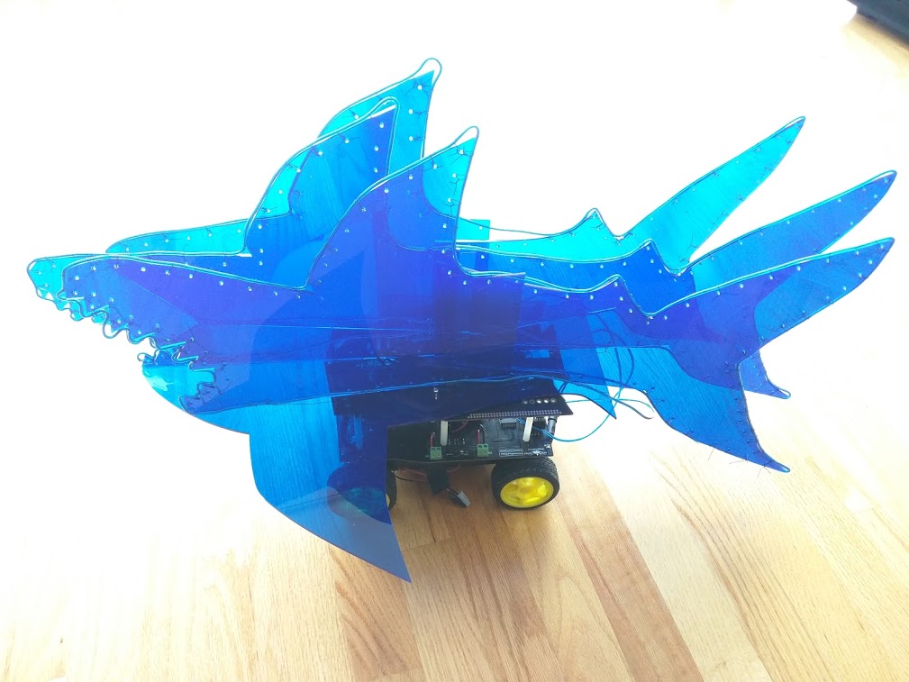
Once you finish, your body should be looking good with the el-wire affixed!
Improvements
As with every project, if I could do it all over again, I would do it better. My wife did an incredible job on the shark design, but the hole pattern I added isn’t the easiest to attach to the chassis. The slotted design was there to add flexibility, but the vertical shark body occludes some of the best places for screws, so you have to have nimble fingers to slot them inside. Additionally, the ideal location for the back slots are blocked by the piece containing the relays. Feel free to improve upon the design should you cut your own!